technical analysis
technology development
technology education

Jubinski Tekade is a limited liability corporation formed and registered in the State of Washington, USA.
This website © Jubinski Tekade 2015. All rights reserved.


Our customers don’t commit their money to acquire systems that will be parked in a driveway for the neighbors to admire. Our
customers are looking for solutions to significant problems and, in order to provide appropriate solutions, we work hard to
understand those problems and our customer’s requirements.
We have designed and built systems tended by operators who turned knobs and pushed buttons, operators who watched video
screens to monitor software-controlled automated operation, and autonomous systems that had no operators.
Drawing on extensive experience with systems covering a wide range of capability, technical sophistication and cost, we are well-
equipped to develop a system that will meet your needs and fit into your operational environment. And, having worked in the real
world, we know that a solution that doesn’t meet your technical requirements or can’t be built in time or is unaffordable isn’t really a
solution.
We take a hands-on approach and are capable of taking a project from the initial planning stages, through engineering design,
fabrication, testing, delivery, user training and technical support. When it makes sense to do so (or when schedule demands it), we
can handle many fabrication, integration and test procedures in-house. Otherwise, we can rely on the extensive selection of
machine shops, specialty fabrication houses, shipyards, marine research programs, calibration/test facilities and marine
instrumentation suppliers here in the Seattle/Puget Sound area.
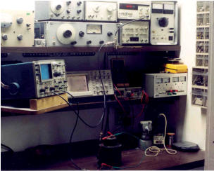
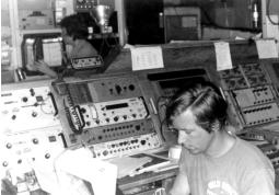
Electronics Laboratory on the Hawaii Institute
of Geophysics R/V Kana Keoki, 1975. Don
Hussong is at the ASR33 teletype. Ann Meloy
is at the wind speed/direction recorder (photo
by Steve Dang, Hawaii Institute of Geophsics)
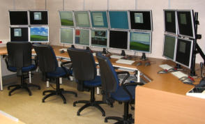
Survey Room Master Console Station on board the
IFREMER N/O Pour Quoi Pas?, 2005 (photo by Paul
Jubinski, Reson)
Launch of the AMOS-I Autonomous Marine
Observation System, on board University
of Washington Applied Physics Laboratory
R/V Jack Robertson, 2011. (photo by Paul
Jubinski, Reson)
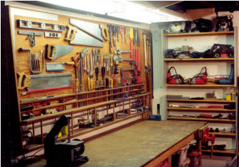
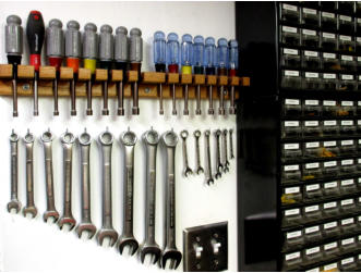
The workbenches and shop areas at Jubinski TEKADE LLC are well-
equipped and organized but rarely this clean. (We thought that it would
be worth the effort to clean it up one time for a good set of pictures.)

The following are examples of systems and system components that were integrated or developed to address
specific customer needs, often on tight schedules and within limited budgets. Paul Jubinski played a primary role in
each of these examples but the work on many of them predate the formation of Jubinski TEKADE LLC.
Customized Controller providing a simplified interface for an Ethernet-controlled multi-beam sonar.
Low-cost proof-of-concept bottom-lander for Automonous Marine Observation System
Portable version of Reson SeaBat 7150-C 24 kHz deep-water multibeam mapping sonar
Hybrid forward-looking multibeam sonar for the Cabled Observatory Vent Imaging Sonar (COVIS)
Deep-Tow Search/Survey Vehicle equipped with dual SeaBat 7125-AUV multibeam sonars
The Japan Agency for Marine-Earth Science and Technology (JAMSTEC)
developed the Deep Sea Cruising Urashima AUV, which has served as a testbed
for vehicle controls, hydrogen-oxygen fuel-cell power systems and advanced
sensor and sampling technology.
In 2004, the Urashima development team, led by Dr. Satoshi Tsukioka, was able to
greatly improve the survey capability of their AUV through the acquisition of a high-
precision multibeam bathymetric sonar, a Reson SeaBat 7125-AUV. At that time,
the vehicle controller in the Urashima AUV was implemented in an industrial
controller platform that could not support the Ethernet communications necessary to
control the SeaBat system.
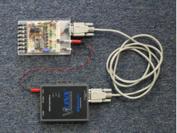
The inexpensive solution to this interface incompatibility was provided in the form of
a customized controller, a compact circuit board with interface circuitry, status LEDs
and an on-board module interpreting tokenized BASIC commands. This circuit
board monitored the DC power provided to the SeaBat system, as well as contact
closures controlled by the AUV vehicle controller. When the SeaBat system was
powered up, the customized controller waited for the SeaBat system to initialize and
load its internally stored operating parameters and then generated a sequence of
Ethernet commands instructing SeaBat system to enable its transmitter and begin
collecting bathymetric data. When the AUV vehicle controller indicated (by
changing the status of a contact closure) that the SeaBat system was to be shut
down, the customized controller issued the Ethernet commands necessary to shut
off the transmitter, properly close the data files and place the SeaBat control
computer into a safe state, ready for power shut-down.
The customized controller was used for several years and then removed when an
upgrade to the Urashima AUV vehicle controller added the Ethernet capability
necessary to directly control the SeaBat sonar system. Removing the customized
controller was a simple matter because its installation had required no changes to
either the Urashima AUV vehicle controller or the SeaBat 7125-AUV system.
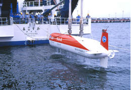
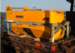
The JAMSTEC Deep Sea Cruising Urashima
AUV being recovered by its suppport vessel,
the R/V Yokosuka. (Photograph courtesy of
JAMSTEC.)
The compact customized controller developed
for the SeaBat 7125-AUV multibeam sonar
system installed in the Urashima AUV. (Photo
by Paul Jubinski, Reson.)
Customized Controller providing a simplified interface for an Ethernet-controlled multi-beam sonar.
Launch of the AMOS-I Autonomous Marine
Observation System, on board University of
Washington Applied Physics Laboratory
R/V Jack Robertson, 2011. (photo by Paul
Jubinski, Reson)
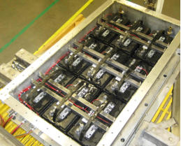
Low-cost pressure-compensated 10
kilowatt-hour battery assembly for the
AMOS-I Autonomous Marine Observation
System. (photo by Paul Jubinski, Reson)
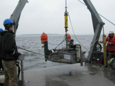
Low-cost proof-of-concept bottom-lander for an Automonous Marine Observation System
In order to study the impact of a proposed installation of tidal energy turbines in
Puget Sound, a monitoring program was set up to gather baseline information on
water characteristics, tidal flows and the behavior of fish and marine mammals.
The budget for data acquisition was modest but workable, assuming that most of
the monitoring instruments could be borrowed and that the cost of setting up
autonomous instrumented seabed platforms could be minimized.
One of the instruments to be used was a Reson 7128-AUV forward-looking
multibeam sonar, oriented so as to look upward from the seafloor to monitor wildlife
passing by in the water column.
The AUV version of the 7128 was selected because it can run directly on 48 volt
DC power and has an Integrated Control/Processor Unit (ICPU) that can log data
internally and configure itself from a table of stored parameters, allowing it to
operate without human intervention. The power consumption of the 7128-AUV was
too high for the sonar to operate continuously over the planned 30-day deployment
period, so the decision was made to collect data 10 percent of the time, i.e., 12
minutes out of every two hours.
The Autonomous Marine Observation System (AMOS-I) consisted of the 7128-AUV
multibeam sonar system, a timer/control unit, battery banks to power the sonar and
timer/controller, and a rugged stainless steel frame that would allow AMOS-I to be
lowered from a deployment vessel to the cobble-covered seabed, survive for 30
days in currents as great as seven knots and then be hoisted back aboard a
recovery vessel.
The timer/controller reused the basic architecture and software from the
customized controller developed for the Urashima AUV, with a precision clock, flux-
gate compass and power relay added to control the 48 volt power to the sonar.
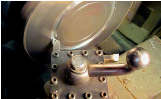
The operating depth of less than 100 meters made it possible to forego the normal
(and expensive) titanium pressure housing and to house the ICPU and
timer/controller in a welded stainless steel pressure housing fabricated from
standard pipe and flange fittings. With only one deployment planned, the required
10 kilowatt-hour battery assembly could be built up using relatively inexpensive
deep-discharge automotive lead-acid batteries. The 12-volt timer/controller battery
and two 48-volt sonar battery banks were secured into a pressure-compensated
housing consisting of a welded aluminum tub filled with lightweight mineral oil and
topped with a sealed neoprene cover.
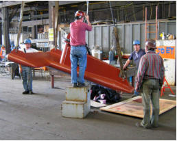
Portable version of Reson SeaBat 7150-C 24 kHz deep-water multibeam mapping sonar
The half-size sonar gondola ready for
shipping at Stabbert Yacht and Ship, the
fabricator in Seattle, Washington, USA.
(photo by Paul Jubinski, Reson)
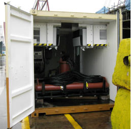
The gondola and the electronics cabinet
inside the cusomized shipping/laboratory
container in the Keppel Gul Shipyard,
Singapore. (photo by Paul Jubinski, Reson)
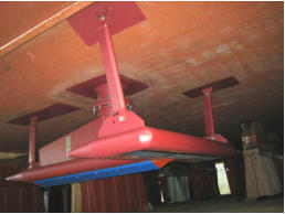
The installed gondola, attached to the moon
pool flange, showing the blue sonar
transducer array modules. The array and
sensor cables are inside the moon pool
pipe. (photo by Paul Jubinski, Reson)
The customer required a hull-mounted multibeam mapping sonar that was suitable
for surveying in water depths as great as 4,000 meters and could be installed
aboard a chartered vessel when needed for particular projects. The vessel initially
used as the survey platform had a 14-inch moon pool and deck space that could
accommodate a 20-foot shipping container. It was not certain that the system
would always be mobilized onto a ship with deck space sufficient to accommodate
the 20-foot container.
The multibeam mapping sonar selected for this application was the Reson SeaBat
7150-C, a 24 kHz multibeam sonar with half-length transducer arrays. The
reduction in the array lengths doubled the linear dimensions of each sonar beam
footprint on the seafloor but allowed the use of a half-sized gondola that could be
stored and shipped inside of a standard 8-foot wide shipping container. The design
of the gondola included a vertical pipe (that would act as a cable conduit) extending
upward from the main body, topped with a flange appropriate for mating with the
flange on a 14-inch pipe.
A standard 20-foot shipping container was outfitted
as a laboratory van, with weathertight personnel
doors, wall and ceiling insulation, overhead
lighting, slide-out air conditioning units,
weathertight cable entries, a floor mount for an
electronics cabinet and space for the half-size
gondola on its shipping frame.
The 7150-C sonar transceiver electronics and
sonar processing electronics were arranged in a
custom configuration with special mountings that
allowed them to be installed in an industry-
standard electrical enclosure. An installation on a
vessel that did not have space for the 20-foot
laboratory van might require that the electronics
cabinet be located on an open deck, so an
electrical enclosure was selected that offered
weathertight door seals and all stainless steel
construction. The basic enclosure then received a
stainless steel air conditioning unit, water tight
cable entries for the power, Ethernet and sonar
array cables, and a stainless steel base with lifting
eyes and bolt holes.
In the initial installation, a short length of pipe with a standard 14-inch pipe flange
was installed at the bottom of the vessel’s moon pool. The gondola was positioned
below the moon pool, the array and sensor cables were run up through the
moonpool to the ship’s main deck and the gondola was lifted into position, its flange
was mated with the moon pool flange and secured with bolts. Struts were then
added to the tail and wingtips to insure mechanical stability. The array and sensor
cables were fed into the laboratory van, connected to the electronics cabinet and
the system was ready for test and calibration.
When the initial use of the system ended, the gondola was removed by commercial
divers, packed into the laboratory container and placed into storage. When the use
of the system was again required, the laboratory van was placed back on the deck
of the vessel and the gondola was reinstalled by commercial divers.
More information on this system (including a video showing the system while it was
being built) can be seen here, at the Teledyne-Reson web site.
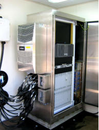
The sealed, climate-controlled
electronics cabinet, (containing
the master operating console,
transceiver electronics and
processing electronics for the
sonar) inside the cusomized
shipping/laboratory container.
(photo by Paul Jubinski, Reson)
Hybrid Forward-Looking Sonar for the Cabled Observatory Vent Imaging Sonar (COVIS) System
Deep-Tow Search/Survey Vehicle equipped with dual SeaBat 7125-AUV multibeam sonars
In the year 2000, the Woods Hole Oceanographic Institution’s ROV Jason was used
to collect sonar observations of a black smoker vent in the Endeavour Field of the
Juan de Fuca Ridge. The results of this experiment confirmed that a vent imaging
sonar could be a valuable component of the NEPTUNE Canada Cabled
Observatory System (now part of Ocean Networks Canada), which was then in the
planning stage. In 2009, the National Science Foundation accepted an engineering
proposal for the development of a Cabled Observatory Vent Imaging Sonar System.
An engineering team at the University of Washington’s Applied Physics Laboratory,
led by Russ Light, selected Reson to provide the high-resolution sonar system that
would serve as the heart of the COVIS System.
In order to satisfy the COVIS operational requirements, the Reson AUV Systems
Team developed a hybrid sonar that incorporated both the 400 kHz narrow-beam
projector used in the SeaBat 7125 bathymetric sonar and the 200 kHz / 400 kHz
wide-beam projector used in the SeaBat 7128 forward-looking sonar. The AUV
version of the SeaBat sonar was chosen because:
o
its Integrated Control and Processing Unit was compact and could be
packaged in a 6,000 meter depth-rated titanium pressure housing,
o
it could be operated using 48 volt DC power,
o
it can configure itself at power-up from stored operating parameters,
o
it has the capability to store data internally, and
o
it can transfer recorded data, be controlled and be monitored via
Ethernet
The particular needs of COVIS, with its long, unattended deployment, meant that
some important customizations were required:
o
the standard system disk drive and data storage disk drives were
replaced with high-reliability single-level cell solid state storage devices,
o
a software-controlled switch was added to allow the output of the sonar
transmitter to be routed to the projector element that was appropriate
for each of the COVIS data collection modes,
o
Eric Schug (Reson senior electronics technican) modified the dual-
frequency receiver to provide a phase monitor for the signal that was
actually transmitted into the water,
o
a hardware-based Ethernet keyboard/video/mouse extender was
installed, giving shore-based personnel a means of direct
communication with the ICPU computer that could be used if the
computer failed to boot up on power-up.
The COVIS System was put into place on the seafloor by the Canadian ROPOS
ROV in September, 2010 and worked for about one month, until the failure of an
underwater cable blocked the transfer of the COVIS data to the NEPTUNE Canada
network. The COVIS System resumed operation in September, 2011, after ROPOS
replaced the failed underwater cable with an imroved version. In this video, Russ
Light describes the COVIS System, its operation and the value of the data that it
collects.
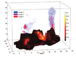
The COVIS System continued to monitor the activity of the black smoker vent,
sending data sets ashore several times each day, until the system was recovered
for major maintenance in September, 2015. The COVIS data have been used to
produce animations and analyzed to study the behavior of the hot water plume.
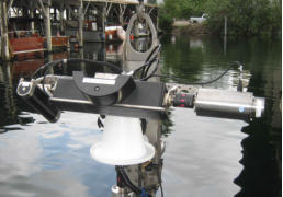
The narrow beam 400 kHz projector, the
wide beam 200 & 400 kHz projector, the
128/256 channel receiver and the 3-axis
rotator assembly at the top of COVIS.
(photo by Paul Jubinski, Reson)
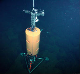
The COVIS instrument package, being
placed by the ROPOS ROV onto the rough
volcanic seafloor in the Endeavor Rift Valley
during installation in 2009. (photo courtesy
of Project NEPTUNE Canada)
An image produced from COVIS data,
showing the hot water plume exiting the
black smoker vent and the diffuse flow of
hot water from the seafloor (from an EOS
Report by Peter Rona and Russ Light)
(More information coming soon.)